


Parameters of IGBT thermal resistance
Parameters of IGBT thermal resistance
Thermal design is very important in the selection of IGBT, which is related to the reliability and lifespan of the module. The thermal resistance and thermal impedance parameters of the module are the basic elements for evaluating the system's heat dissipation capacity. Here, we will briefly discuss the thermal resistance and thermal impedance parameters and testing methods
Thermal resistance and thermal impedance
Firstly, refer to the parameters regarding thermal resistance in the specification sheet

Obviously, this is a steady-state thermal resistance parameter
The definition of steady-state thermal resistance is the formula Rth=△ T/P (the ratio of the temperature difference between the two ends of an object and the power of the heat source when heat is transferred), which can be understood by referring to our familiar electricity. That is, △ T is the potential energy difference, Rth is the blocking effect of thermal conductive materials on heat, and the heat dissipation power P is similar to the conducted current
We know that when DC is applied in a circuit, only the effect of resistance needs to be considered, and AC will introduce the influence of inductance and capacitance; In the thermal circuit, if the heat dissipation power is constant, that is, the chip generates constant heat, then generally only the effect of the steady-state thermal resistance Rth needs to be considered. However, the instantaneous power P generally varies. At this time, the specification book provides the concept of transient thermal resistance Zth, which is a function of time
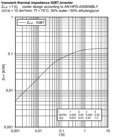
The transient thermal resistance is a function of time, indicating that there is also the role of heat capacity, which is the heat capacity in high school physics
Therefore, during the conduction process of heat in the heat dissipation layer, it is simultaneously affected by thermal resistance and heat capacity
Just like a circuit, how can we describe this hot circuit
Hot Road Network Model
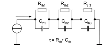
The first type is the continuous network hot path model, also known as the Cauer model
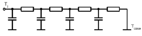
This model is easy to understand, and each layer of heat dissipation material (chip, chip connection, substrate, substrate connection, bottom plate, etc.) can be represented by corresponding RC units, intuitively reflecting the properties of heat transfer from the chip to the materials of each layer of the heat sink, as shown in the following figure:
图片来源:Mentor T3ster 宣传材料
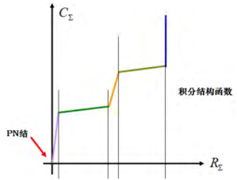
The diagram above is very intuitive. Each layer of material corresponds to a corresponding RC model, which can be represented by a structural function. As for how to obtain the structural function, we will discuss it later
Second type: Local network hot path model, Foster model
Unlike the Cauer model, RC nodes no longer correspond one-to-one with thermal conductive materials, and network nodes have no physical meaning. The coefficients in the above model can be easily obtained from the heat dissipation curve. Therefore, this model is often used to analyze and calculate the temperature distribution of the module. The thermal impedance curve equation can be approximated as:
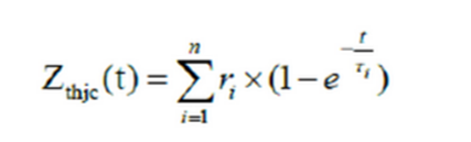
The transient thermal impedance in the specification sheet is based on this model. Looking back, it is easy to understand the transient thermal impedance curve in the following figure

The heat dissipation characteristics of the module
Borrowing a picture from Semicon Power Electronics
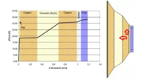
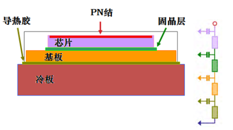
The heat dissipation and typical curve of each layer of the module without a bottom plate
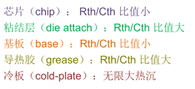
In one-dimensional models, we intuitively understand that thinner copper layers have lower thermal resistance. However, in three-dimensional models, heat flow also has lateral transfer, and if the lateral diffusion ability is weak, the thermal resistance will be relatively large
For example, in the above figure, the heat of the chip is transmitted in the direction of the arrow. The stronger the lateral conductivity of each layer, the wider the heat flow path of that layer, and the lower the corresponding effective thermal resistance (this explanation is a bit rough). Therefore, the heat dissipation model presented in the above figure is not difficult to understand
In order to allow heat to pass through layers with poor thermal conductivity, a corresponding high potential energy difference (temperature difference) must be established. This requires a layer with good thermal conductivity on top to increase cross conduction
Transient thermal impedance test
We know that the thermal resistance formula is Rth=△ T/P
Transient thermal impedance can be calculated using a special algorithm based on the temperature change process
Therefore, before measuring thermal resistance, it is necessary to find a way to quickly collect the junction temperature of the chip
Method for measuring junction temperature:
·Thermocouple: Surface mounted thermocouples on chips alter the packaging structure of power devices, resulting in differences from normal operating conditions, especially when the chip area is relatively small, which can have a greater impact;
·Infrared irradiation: black modules that require special processing to directly detect chip temperature during operation, also changing module structure;
·Electrical testing: Under low current, there is a linear relationship between junction voltage and junction temperature (an inherent property of semiconductors). This testing method has high accuracy and good repeatability
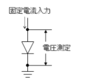
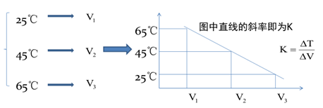
Principle of testing chip junction temperature using electrical methods
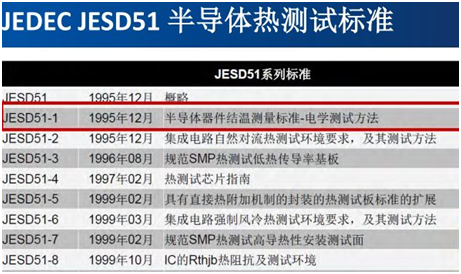
Reference standard: JESD51-1
Measure transient thermal resistance based on chip temperature changes:
Recommended T3ster testing method:

Reference standards
JEDEC series standards
Summary
The above thermal resistance test, combined with PCmin (minute level power cycle test), can analyze the accelerated aging degradation of heat dissipation materials and welding layers. At the same time, thermal resistance testing is an important reference for thermal design. The above introduction is just an introduction, briefly discussing what thermal resistance is and how to test it. As for how to design it, everyone shows their own skills
reference resources:
Solution for Transient Thermal Testing of Electronic Devices by Luo Xiaochuan
How to understand the thermal resistance and thermal resistance of IGBT
And other related materials
Talent Recruitment | Contact Us |

Copyright © 2024 Megateam Semiconductors(Shenzhen) Co., Ltd. All rights reserved